This article describes part of a project called Solar Powered Garage
Some time ago I decided to install solar panels in my garage to charge a battery that I use for powering lights. While browsing through devices from recognised manufacturers, a thought suddenly occurred to me: could I make such a device myself?
I had to admit that my experience in electronics isn't impressive. Taking into account that my only experience in the area of electronics related to batteries was building my own ~16V LiIon package out of 18650 cells with a cheap BMS, I decided to start from something easier. I started looking on the Internet for DIY designs and found 1kW Fugu Controller. The author of the design claimed to use it in his own house for a relatively large PV installation.
Electronic parts and their replacements
Some parts for this project were discontinued or are hardly available. The project was published four years ago, so it might have happened. Other parts are easily available, but not from European warehouses. The author comes from the Philippines. He admits in the project description that he used parts available on the Asian market.
Taking that into account, I decided to order some integrated circuits from AliExpress and replace others with European equivalents.
At this point I already had PCBs for this project on my desk, so I had to look for replacements available in the same packaging. This is a lesson for next time to verify the bill of materials before ordering PCBs.
Possible problems with AMS1117
I couldn't find AMS1117 in stores where I was buying parts. My first thought was that the part was discontinued and I had to look for a replacement. However, after spending some time looking for replacements, I found an article about faulty samples of this part. Thanks to this reading I found that this part is still in production, but due to its popularity many pieces are faulty or do not meet the parameters. I assume they must be counterfeit, because I couldn't believe that original parts that are so popular would be produced in such a sloppy way.
After reading that article, I decided to select some substitute from a reputable company. I decided to use LD1117 from STMicroelectronics.
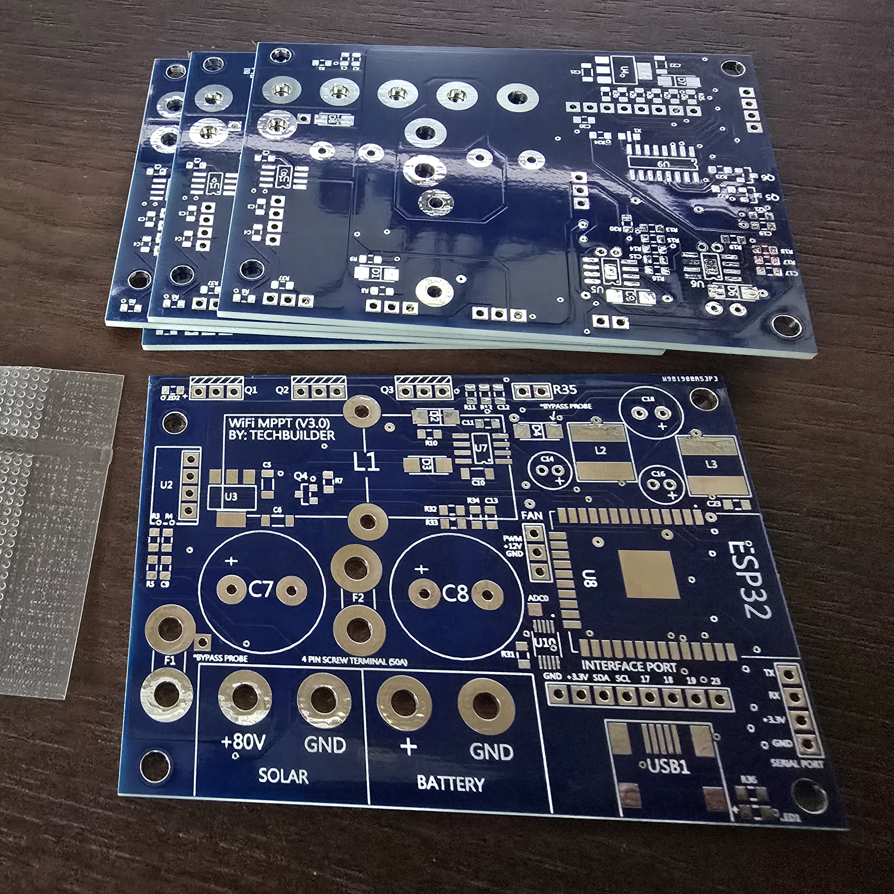
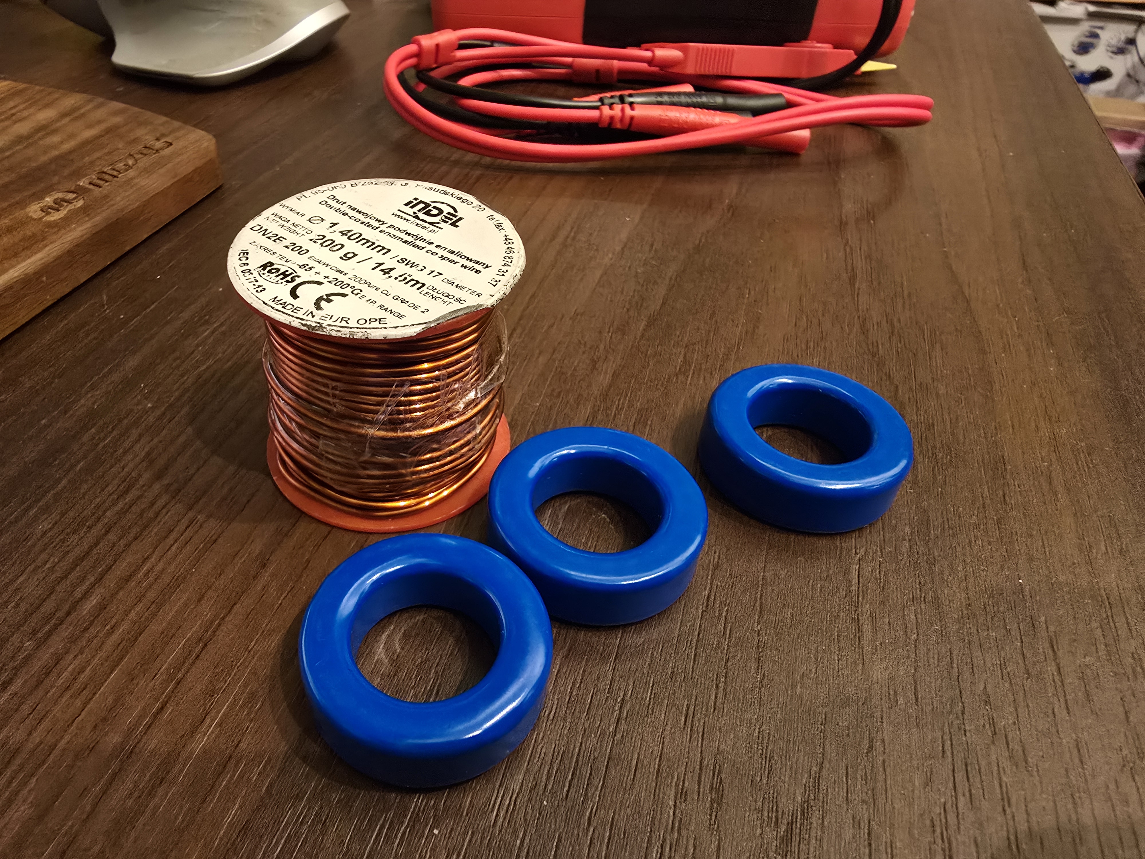
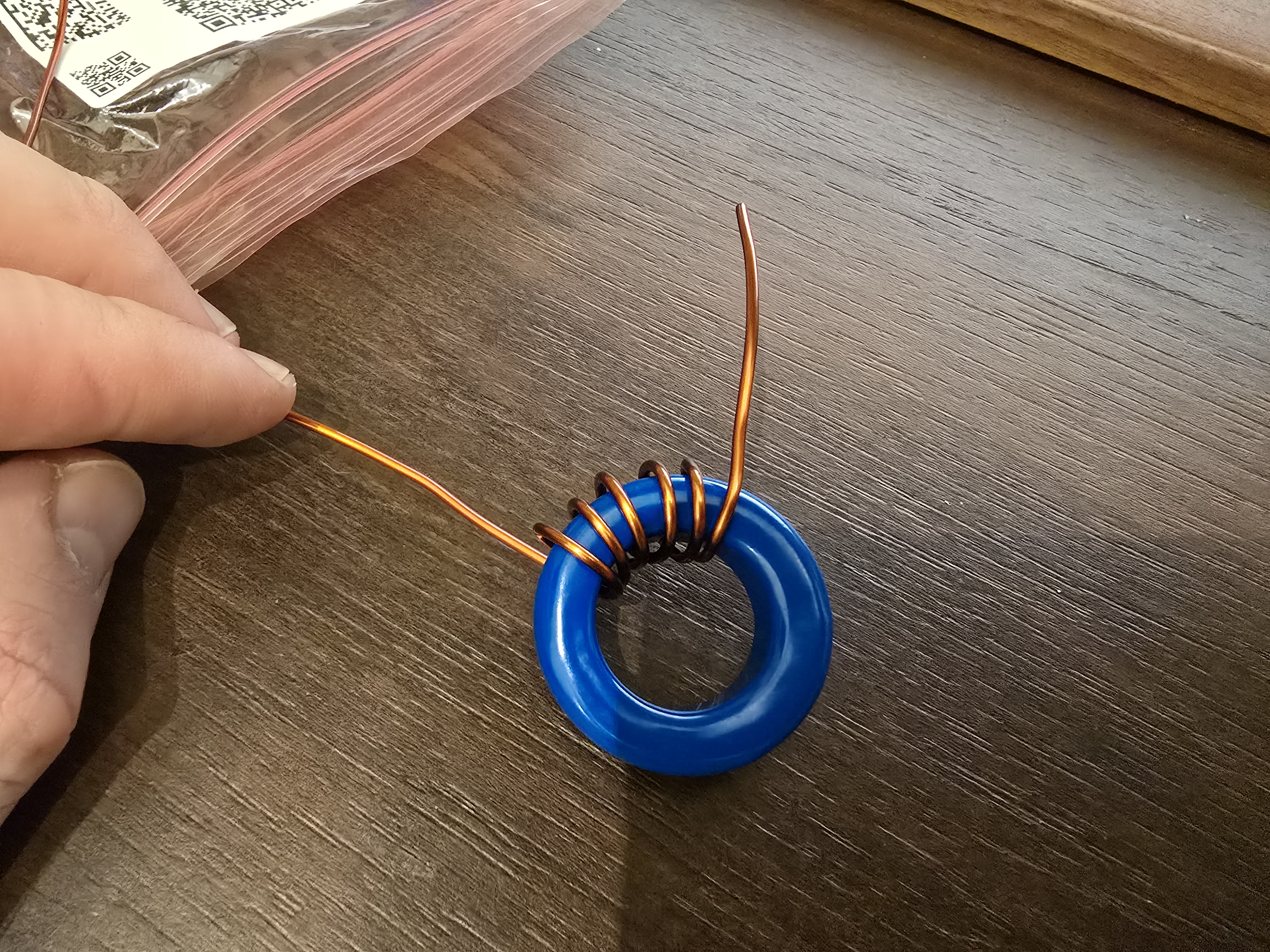
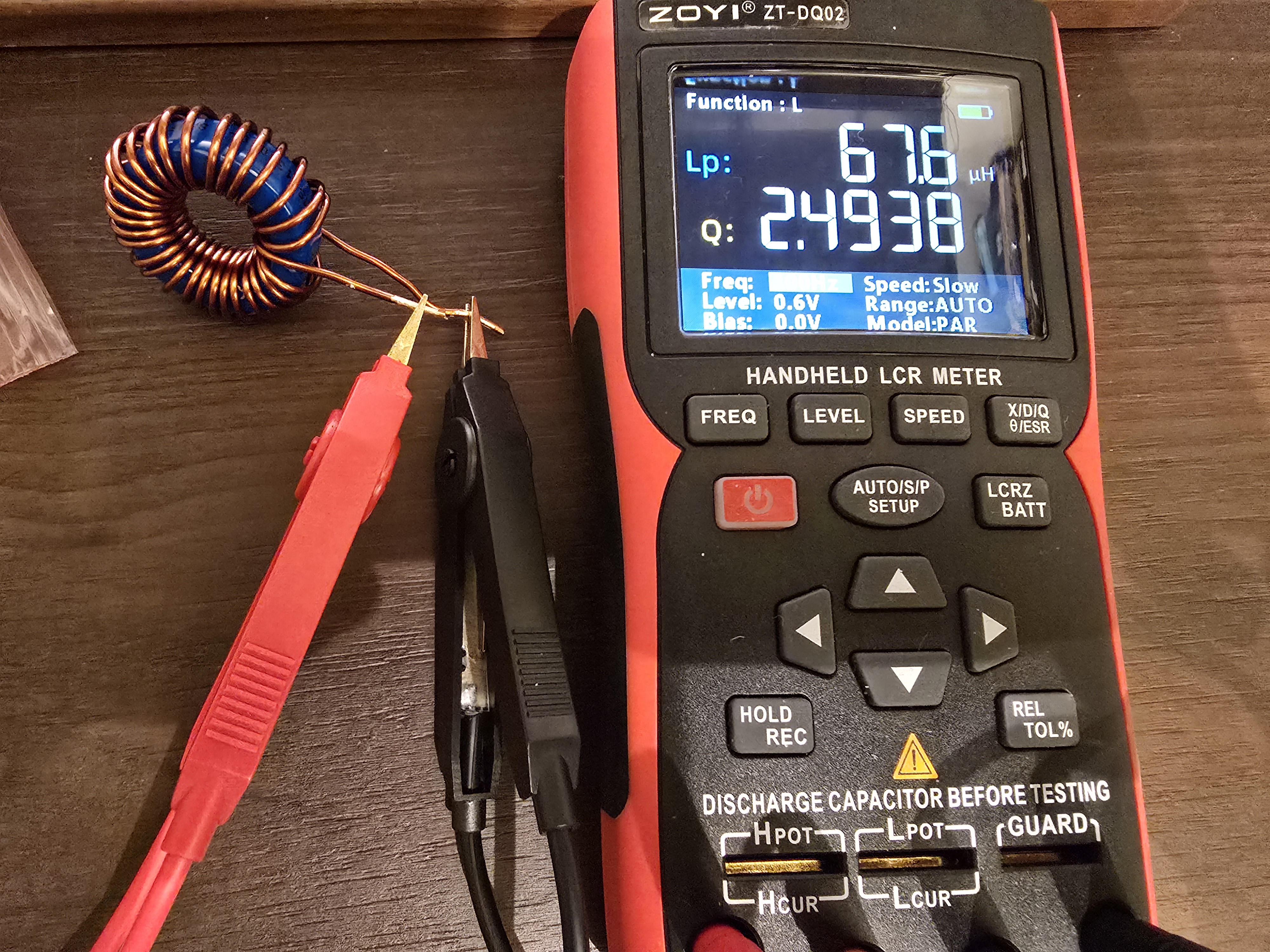
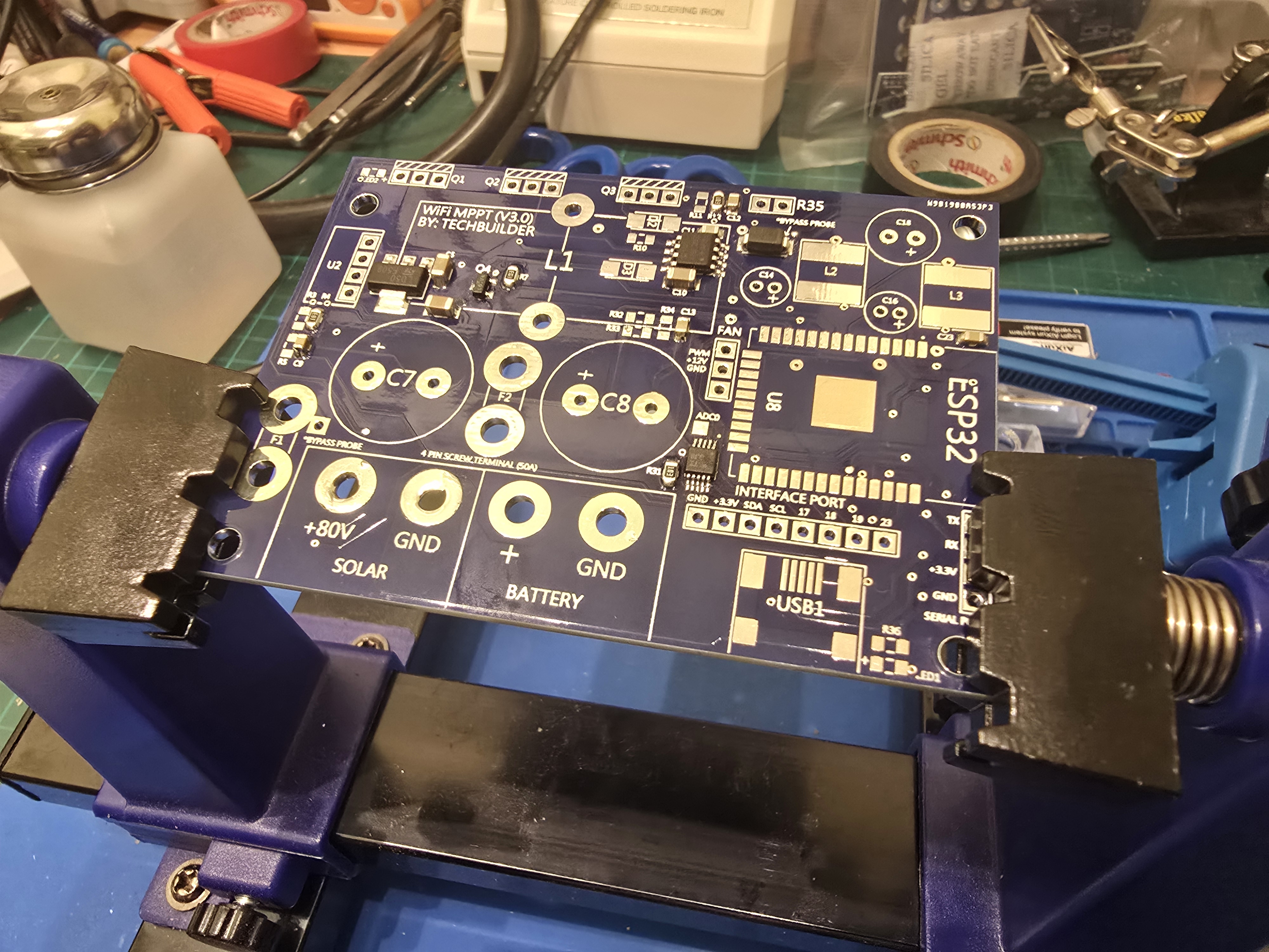
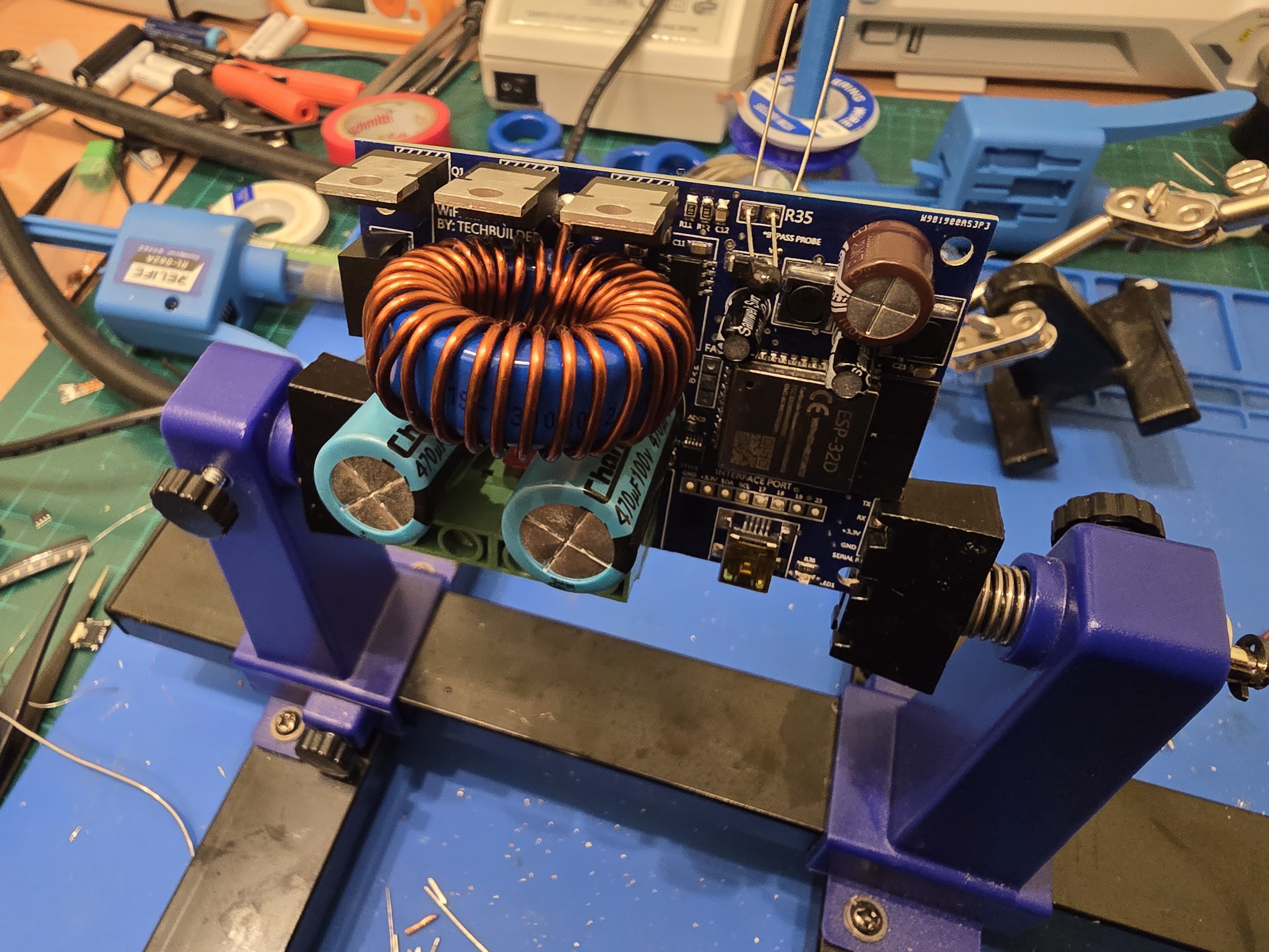
PCBs and Coil Winding
The most interesting aspect was winding my own coil. I couldn't find exactly the same core and wire as the author had, but thanks to an online calculator, I've managed to wind one on my own. Assuming that my Zoya inductance meter is accurate enough, I was able to build a similar one with quite accurate parameters.
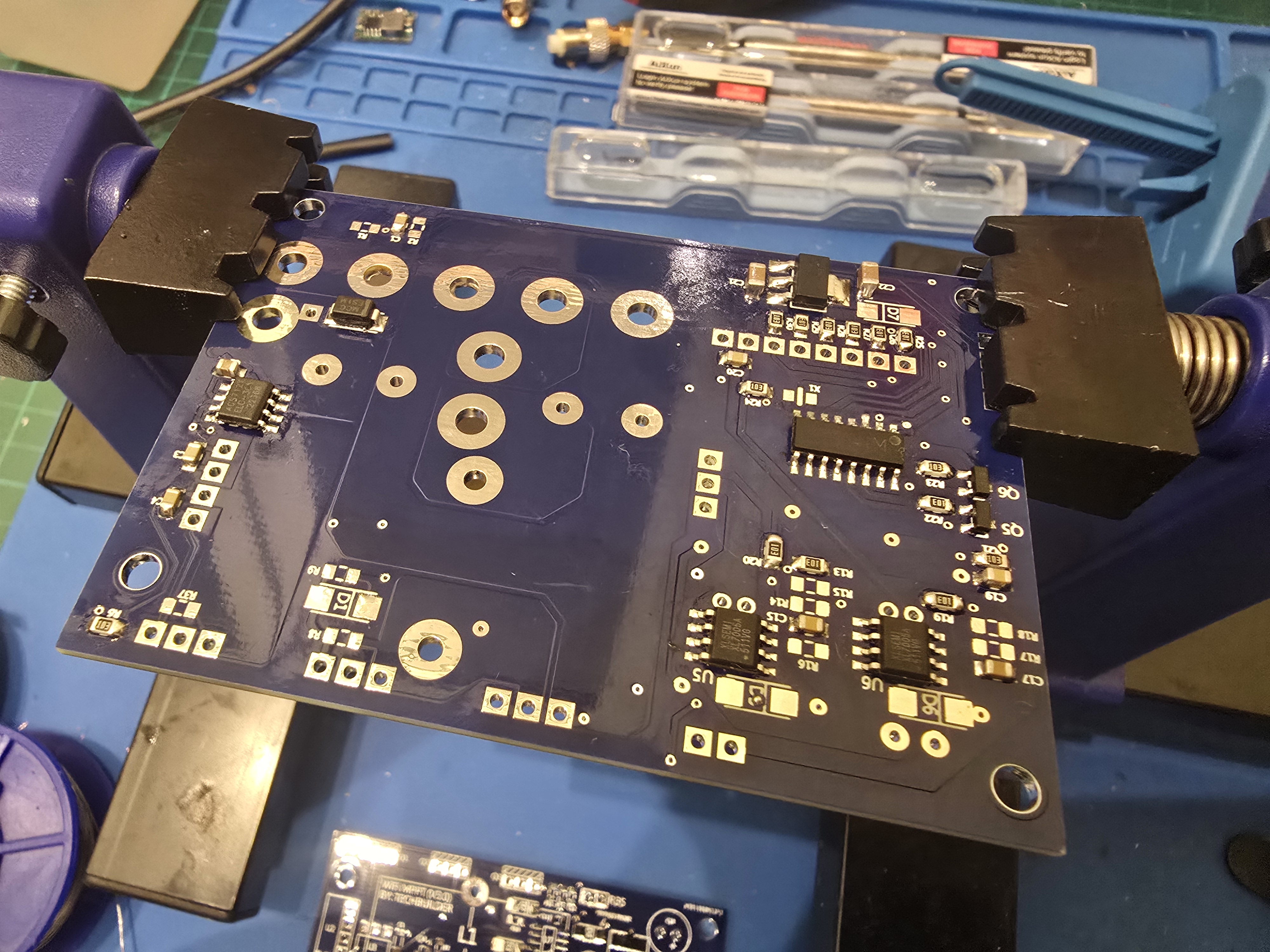
Soldering
I'm quite familiar with SMD soldering. For training I soldered a few components using a soldering station, but most of the work was done with hot-air. Here are some photos during the assembly process.
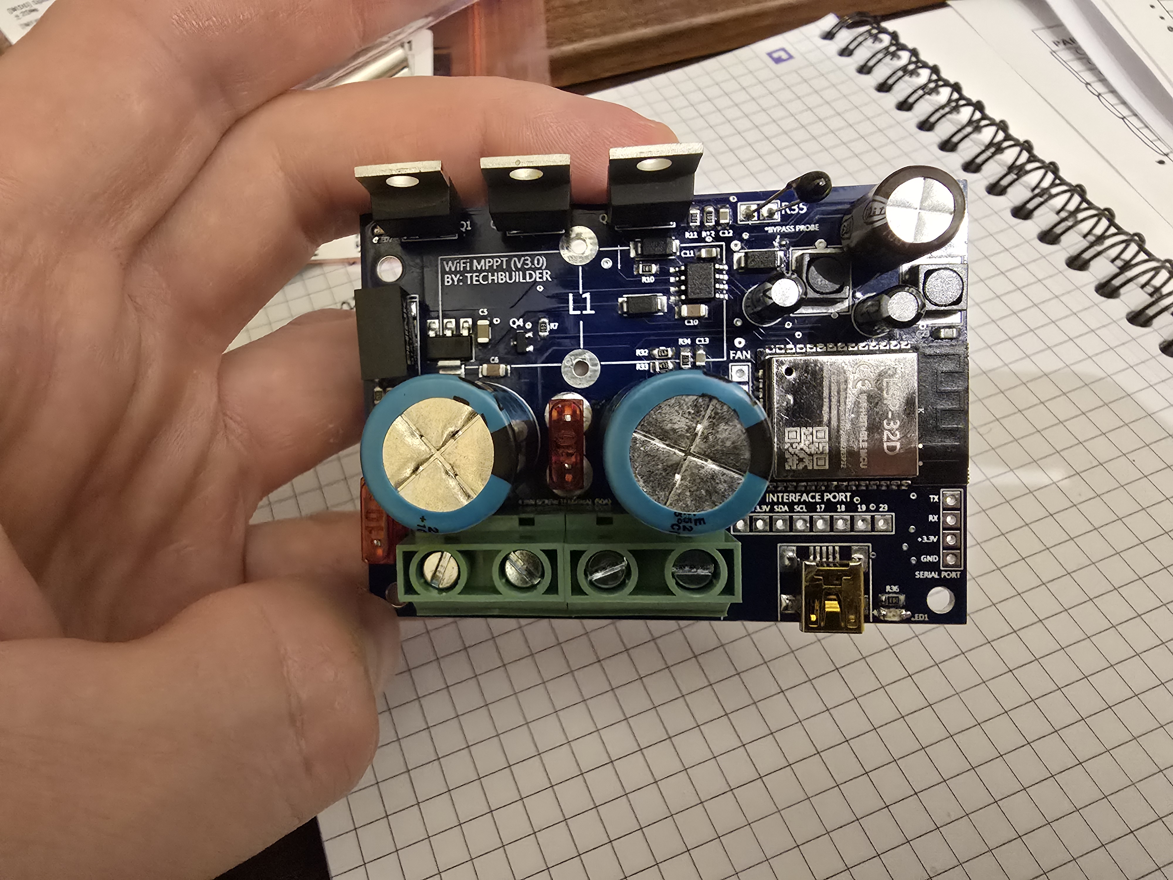
After connecting the board to the computer via USB, a USB-to-serial converter appeared on the host. It was the first good sign. Unfortunately it wasn't able to communicate with ESP32. All connection attempts failed. I guessed that I probably didn't solder ESP32 well enough. I fixed that by resoldering all pads with an appropriate soldering iron tip.
Another thing I had to correct was ADS1115. Resoldering it was a nightmare due to its small package, but finally I managed to do it properly. In most cases this worked fine: putting solder paste on pads, next placing a part there and then melting paste with a hot air gun. In case of very small parts it's way better to first melt soldering paste, then put the part in place and finish the process by heating it once again with a hot air gun.
Flashing firmware
This project unfortunately looks abandoned. I haven't checked software quality carefully before ordering PCBs, so when I did that I found that many parts were failing to compile due to outdated dependencies. I decided to turn off some functionalities I don't need now (like Bluetooth telemetry). After some tries, I compiled original firmware with Arduino IDE and flashed it onto ESP32. After connecting a power supply and cells to the controller, it started charging the battery. However, there are some issues.
Possible issues in the software
There are a lot of delays across the code. These are placed (but not the only ones) when the buck converter isn't controlled. The lag between changing the input voltage and the reaction of the system (regulating current) can be observed on the screen and telemetry. Let's assume that the system will hang on I2C reading or writing (sensors and display are on this bus). Then PWM controlling the buck is at the same level which can result in running too high current. What is a possible solution? Sensors and PWM should be handled with interrupts. Also some kind of watchdog should shut down the device and turn off the converter when it suspects the device hung. Telemetry which relies on UART also can block on buffer overflow.
Reaction time to the input voltage or current changes also wasn't impressive. I did some tests with a power supply connected as solar and checked how it behaves when voltage rises rapidly. I'm going to prepare a separate post with diagrams from an oscilloscope showing how it behaves. Maybe I'll manage to compare it with Victron Energy Smart Solar that I also own.
I've decided that running such a device is too dangerous. Batteries, especially lithium batteries, can be very dangerous when they are charged or discharged improperly. Although my battery has a proper BMS that protects it well, I didn't want to take a risk.
I did some short-term (up to one hour) tests under my control and decided that I need to write new firmware in a proper way (non-blocking, with interrupts, utilizing advanced uC features like DMA for passing data between peripherals, watchdogs etc.)
I have already started this effort with new shiny Rust esp_hal. I'll present progress in further blog posts.
Summary
My plan is to use the solar controller for way smaller currents and voltages than it was designed for. For this reason, I'm going to give this design a chance. I'll write completely new, non blocking and better protected firmware. In the next phase I'll try to replace my Victron Energy 75/10 that works well with my small PV installation with a new device.